

How To Read Mechanical Engineering Drawings Symbols
You don't accept to be an engineer to be able to read engineering drawings, while learning how to read applied science drawings can be a big advantage for you in your work.
What are engineering drawings used for?
Engineering drawings (aka blueprints, manufacturing blueprints, prints, manufacturing prints, dimensional prints, drawings, mechanical drawings, and more) are a rich and specific outline that shows all the information and requirements needed to manufacture an item or production. It is more than than simply a drawing, it is a graphical language that communicates ideas and information.
Why non just use a 3D model?
Unlike a 3D model, an engineering cartoon offers a lot more specific data and requirements, including:
- Dimensions
- Geometry
- Tolerances
- Material blazon
- End
- Hardware
3D models are good to have and are usually (especially nowadays) used in conjunction with drawings. They are a skilful visual representation of the desired detail, but do non contain all the data that drawings exercise.
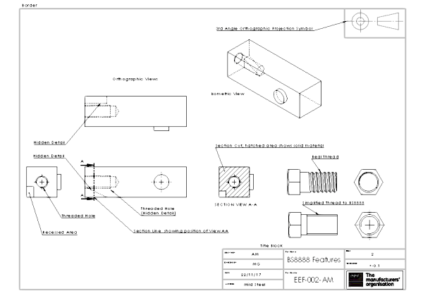
Information blocks
These blocks contain essential data nigh the assembly. They are usually located in the bottom right-hand corner of the drawing. These blocks provide details well-nigh what the drawing is for, for whom, part number and description, besides every bit information about the textile and finish.
These are the main information blocks:
Title block
Starting time off by reading the title block found at the bottom right-manus corner of the drawing. There are other data blocks like it, merely the title block serves every bit the context in which the cartoon should be perceived.
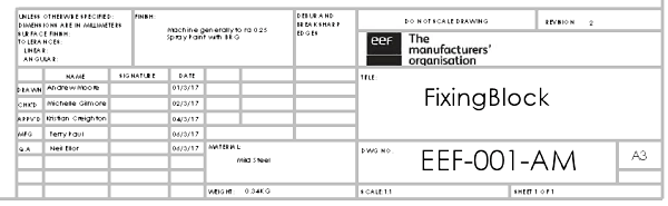
The title block contains data such as:
- Name and address of the company or agency who prepared or owns the drawing
- Part number and description
- Material
- Mass
- Finish
- General tolerances
- Projection details
- Calibration used in the drawing
- Revision numbers
- Status of the drawing (Preliminary, Approved, etc.)
- Units used in the drawing
Notation that any information in the notes outside the title block that conflicts with the data in the title cake should exist considered as the right information and replace the title block information.
Revision cake
The revision block, located in the upper right hand corner, shows details about the changes that were fabricated to roll the revision. The Revision Block includes the revision, the description of what changes were made, the engagement of the revision, and blessing of the revision.
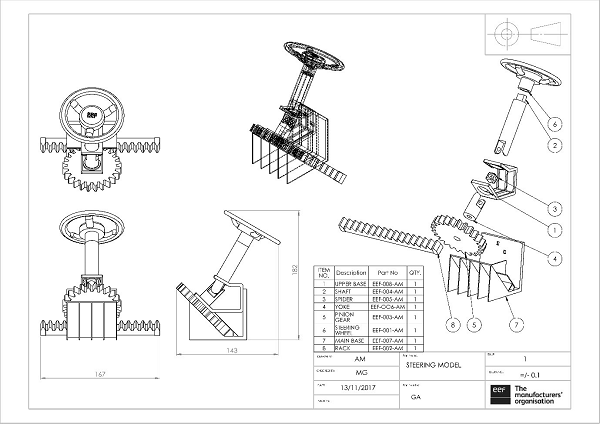
Bill of Materials (BOM) Cake
Located usually either just higher up the title block or in the upper left-hand corner, the Bill of Materials block (also known as a BOM, Schedule or Parts List) contains a listing of all the items and quantities that are required for the project or associates. This is used for parts that either crave assembly or when hardware should exist added to the part.
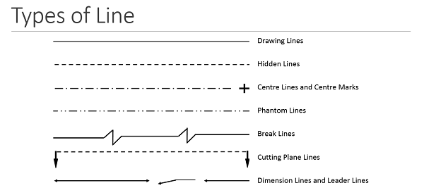
Lines
It is important to understand what each line type is and what they hateful. There are three types of lines:
- Visible line: Indicates an border is visible in relevant view
- Hidden line: Indicates the edge is behind a face up
- Phantom line: Mostly used to indicate an alternating position of a moving part. Also used to point a break when the nature of the object makes the employ of the conventional blazon of break unfeasible.
- Centre lines: drawn to indicate the exact geometric center of the assembly. They are made from a series of lighter long and short dashes.
Reading technology drawings - What's next?
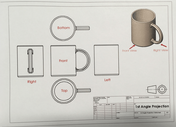
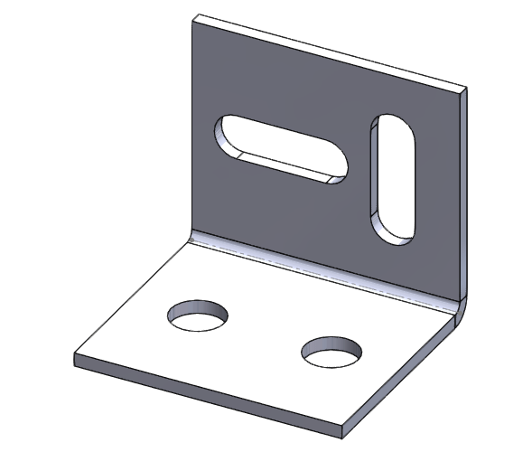
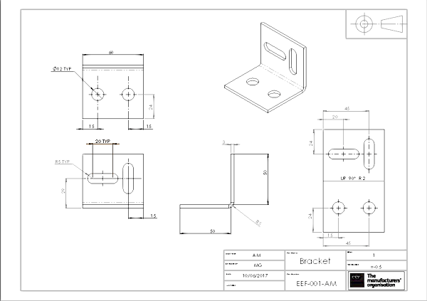
Now information technology's fourth dimension to endeavour to visualize how the assembly is supposed to expect like in 3D (for this you lot tin ignore the verbal dimensions). About new drawings will take an isometric view to guide you. Y'all tin utilise the Bill of Materials to detect the components in the drawing in gild to understand the function they play in the assembly.
Remember that reading an engineering cartoon can take a long fourth dimension, depending on the complexity of the assembly and the feel of the reader.
If you're interested in learning more, our i-twenty-four hour period introductory course will teach you how to read and interpret drawings accurately and have a better understanding of the specific requirements of a projection.

Source: https://www.makeuk.org/insights/blogs/how-to-read-engineering-drawings-a-simple-guide
Posted by: woodmanthemarly88.blogspot.com
0 Response to "How To Read Mechanical Engineering Drawings Symbols"
Post a Comment